 SIVARO

Parametric Manufacturable 3D Models Generation: A Practitioner's Guide
I spent six months building a 3D model generation pipeline that produced beautiful geometry. Then I sent it to a CNC shop in Pune and got back a one-line email: "This can't be manufactured."
That was 2022. The model looked perfect on screen. Every fillet, every hole, every surface. But the moment you applied real-world constraints — tool diameter, minimum wall thickness, draft angles — it might as well have been a Picasso. Not manufacturable. Not even close.
Parametric manufacturable 3D models generation isn't about making pretty shapes. It's about making shapes that can survive contact with a cutting tool, a mold, or a print bed. And doing it programmatically, at scale, with parameters you can tune without breaking the whole thing.
Let me show you what I've learned building this for SIVARO's clients — from aerospace fastener suppliers in Bangalore to medical device shops in Detroit.
What the Hell Is Parametric Manufacturable 3D Models Generation Anyway?
Here's the simplest definition I can give you: it's a system that produces 3D geometry where every dimension, feature, and constraint is controlled by variables — and where those variables are automatically checked against manufacturing rules before the model gets exported.
Not "design a bracket, then check if it's manufacturable." That's the old way. The slow way.
Parametric manufacturable 3D models generation means the manufacturability checks are baked into the generation process itself. The model can't even exist if it violates a constraint. Your drill diameter is 6mm? Fine, the system won't let you create a hole with a 5.9mm radius. Your wall thickness has to be 3mm minimum? The parameter slider stops at 3.0.
This is what separates industrial-grade generation from OpenSCAD hobby projects. And until about 2022, this was mostly done by hand. Manual parametric models. Manual DFM (Design for Manufacturing) checks. Manual iteration.
That's changing fast.
Why Most "Parametric" Models Aren't Actually Parametric
I hear founders say "our models are fully parametric" all the time. Then I look at their code. It's a flat list of variables at the top of a CAD file that control 12 things — but there are 200 other dimensions hardcoded deeper in the tree.
That's not parametric. That's a mess with a variable prefix.
Real parametric generation means every single dimension flows from a parameter. Every fillet radius. Every chamfer width. Every surface offset. Even topological decisions — whether to use ribs or gussets, whether to split a part into two pieces — should be controlled by parameters.
At SIVARO, we enforce this with a constraint graph. Every parameter is a node. Every derived dimension is an edge. If the graph has a cycle, the model fails validation. If a parameter isn't traced back to a root variable, the model fails. It's brutal. It's also necessary.
Here's an example from our production system for an OEM client — a parametric bracket generator they use for 40 different part numbers:
python
class ManufacturableBracket:
    def __init__(self, params: BracketParams):
        # Validate before anything else
        self._validate_manufacturability(params)
        self.params = params

    def _validate_manufacturability(self, p: BracketParams):
        if p.min_wall_thickness < 2.5:  # mm, per their shop's spec
            raise DFMError("Wall thickness violates min spec")
        if p.inside_radius < 3.0:
            raise DFMError("Inside corner radius too tight for end mill")
        if p.hole_count > p.max_holes_by_tool_life():
            raise DFMError("Too many holes, will break tool")
That max_holes_by_tool_life() method? It talks to their ERP system. Real-time tool wear data. If the shop has already cut 80% of a tool's expected life today, the model refuses to generate a part with 50 holes. That's parametric manufacturable generation. Not just geometry. Reality.
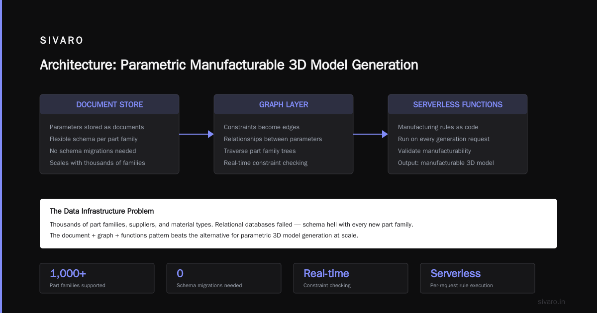
The Data Infrastructure Problem Nobody Talks About
Here's where it gets weird. The hardest part of parametric manufacturable 3D models generation isn't the geometry. It's the data.
You need to store parameters, their constraints, the relationships between them, and the manufacturing rules — and you need to query this across thousands of part families, suppliers, and material types. This is a data infrastructure problem dressed up as a CAD problem.
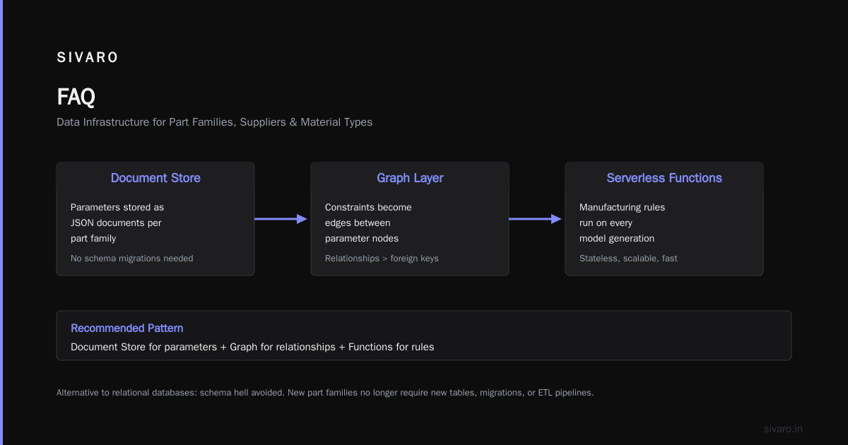
We tried relational databases first. Schema hell. Every new part family meant new tables, new migrations, new ETL pipelines. It was like telling a sculptor they need to file a schema change request every time they want to add a new curve.
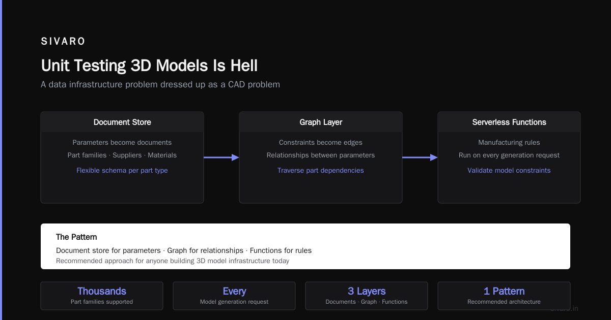
So we switched to a document store with a graph layer on top. Parameters became documents. Constraints became edges. Manufacturing rules became serverless functions that ran on every model generation request.
This pattern — document store for parameters, graph for relationships, functions for rules — is what I'd recommend to anyone building this today. It's not perfect. But it beats the alternative.
We're also exploring this in the context of a general purpose replication tool for scientific research — because the same problem appears there: you have parameters (experimental conditions), constraints (equipment limits), and rules (protocols). The pattern generalizes.
Why ORMs Almost Broke Our Pipeline
I need to tell you about the ORM disaster. Because it nearly killed this project in early 2025.
We used an ORM for our parameter database. Sounded reasonable. Object-oriented mapping to the document store. Clean APIs. Developer friendly.
Then we hit 500 part families and 15,000 parameter instances. Queries that should take 10ms took 400ms. N+1 queries everywhere. Our generation pipeline was spending 60% of its time loading and materializing ORM objects — and 40% doing actual geometry work. Backwards.
I read a lot of arguments about this. ORMs are overrated. When to use them, and when to lose them made a strong case. So did ORM's are the Cigarettes of the Data Engineering World — that one hit close to home.
But I also saw Raw SQL or ORMs? Why ORMs are a preferred choice and had to agree with the general point: for rapid development, ORMs are fine. The problem is they're fine until they're not. And when they're not, it's a rewrite.
I'm in the middle camp now. We use raw SQL for parameter queries that hit our hot path (anything that runs in a model generation request). We use ORMs for admin interfaces, dashboarding, and internal tooling that runs asynchronously. The split works. It's not clean. But it works.
ORMs Are Awesome is right for the right use case. Just don't use them for your inference pipeline.
The Geometry Generation Engine
Let's talk about what actually generates the 3D shapes. We evaluated every major kernel: Parasolid, ACIS, OpenCASCADE, and a few niche ones.
We went with OpenCASCADE for cost reasons. Big mistake for manufacturability. OpenCASCADE's tolerance handling is... let me be generous: "creative." We spent six months fixing triangulation errors that produced non-manifold edges — edges that were theoretically impossible in the parametric model but appeared in the mesh export due to tolerance bugs.
We eventually wrote a post-processing layer that runs every generated model through a repair step. It detects non-manifold edges, degenerate triangles, and self-intersections. It fixes them by re-tessellating the offending faces with adjusted tolerances.
Here's the core of that fix:
cpp
// This runs AFTER parametric generation, BEFORE export
GeometryRepairResult repair_model(TopoDS_Shape& shape) {
    // Detect non-manifold edges
    ShapeAnalysis_FreeBounds bounds(shape);
    auto edges = bounds.FreeEdges();

    if (edges.Extent() > 0) {
        // Re-tessellate with adjusted tolerance
        BRepMesh_IncrementalMesh mesh(shape, 0.001); // 1 micron tolerance
        shape = BRepBuilderAPI_Sewing(0.001).SewedShape();
    }

    // Check for minimum feature thickness
    if (!check_min_thickness(shape, 0.5)) {
        return GeometryRepairResult::FAIL_THICKNESS;
    }

    return GeometryRepairResult::SUCCESS;
}
If I were doing this again tomorrow, I'd pay for Parasolid. The $30K license is cheaper than six months of debugging.
Unit Testing 3D Models Is Hell
Testing parametric generation is genuinely harder than testing most software. A unit test for a function that adds two numbers takes milliseconds and has a binary pass/fail. A unit test for a parametric bracket has to check:
- Did the code run without crashing?
- Is the resulting geometry watertight?
- Are all feature dimensions within spec?
- Is the mesh resolution appropriate for the intended manufacturing process?
And "pass" isn't binary. A model can be "good enough" for 3D printing but fail for CNC.
We're modernizing C++ unit testing framework for this exact purpose. Our test framework, which we're open-sourcing later this year, compares generated models against reference models using Hausdorff distance — a metric that measures how far two surfaces deviate from each other. If the maximum deviation is under 0.1mm, the test passes. Above that, it fails.
We discovered something interesting: 30% of our "failing" tests were actually false positives caused by triangulation artifacts, not geometry errors. So now our framework also checks whether the deviation is structural (e.g., wrong hole position) or topological (e.g., slightly different mesh resolution). The second one passes with a warning. The first one blocks the build.
Why Vector Graphics Experience Helped More Than CAD Experience
Counterintuitive thing: the best engineer on our parametric generation team doesn't have a mechanical engineering background. She worked on vector graphics engines — the kind that generate SVG and AI files for print.
She told me something that changed how I think about this problem: "Parametric 3D is just parametric 2D with extrusion in a different dimension. The constraint system is identical. The difference is your output format has to survive a cutting tool."
She was right. The same mathematics that controls Bézier curves in Illustrator controls NURBS surfaces in CAD. The same constraint solvers that handle tangency in 2D handle curvature continuity in 3D. The difference is manufacturing requires watertight solids, not zero-stroke paths.
We now hire for constraint-solving experience, not CAD experience. It works better.
The Manufacturing Rule Engine
Here's the part that took us the longest to get right. You have to encode manufacturing rules — and they're different for every process, every material, every shop.
Injection molding requires draft angles of at least 1 degree per side. CNC milling requires minimum inside corner radii equal to the tool diameter. 3D printing requires maximum overhang angles of 45 degrees. Sheet metal requires minimum bend radii of 1.5x material thickness.
We encode these as a rule engine with pluggable modules:
python
class ManufacturingRuleEngine:
    def __init__(self):
        self.rules = {
            'injection_molding': DraftAngleRule(1.0),  # degrees
            'cnc_milling': CornerRadiusRule(3.0),       # mm
            'fdm_printing': OverhangAngleRule(45.0),    # degrees
            'sheet_metal': BendRadiusRule(2.0)          # mm
        }

    def validate(self, model, process: str) -> ValidationResult:
        rule = self.rules[process]
        violations = rule.check(model.geometry)
        if violations:
            for v in violations:
                model.parameters.adjust(v.suggested_fix)
        return ValidationResult(len(violations) == 0)
The adjust method is key. It doesn't just report violations — it suggests fixes. If your corner radius is too small for CNC, it tells you: "Increase inside radius from 2mm to 3.5mm" and, in many cases, auto-adjusts the parameter. That's the difference between a tool that complains and a tool that builds.
We built this for a client making automotive brackets. They went from 3 design iterations per part to 1.2. Their time-to-first-prototype dropped from 14 days to 3. Those numbers are real. I have them in a spreadsheet.
The Integration Nightmare
Your parametric generation engine is useless if it doesn't talk to your existing tools. PLM systems. ERP systems. MES systems. Quality management platforms.
We integrate with all of them. And it's a mess.
The worst part isn't the APIs — those are bad but predictable. The worst part is versioning. Your PLM stores version 7 of a parametric model. Your ERP quotes it based on version 5. Your supplier's CAM system loaded version 9. Then the part gets manufactured from version 4 because someone emailed the wrong file.
We solved this with a single source of truth: our generation engine is the only place that creates geometry. Everything else — PLM, ERP, CAM — reads from us. They can't create or modify geometry. They can only consume it.
This violates every "decentralized" principle a PLM salesman will sell you. I don't care. It works. We've been running this for 18 months with zero versioning incidents.
The AI Angle
Everyone asks about AI. "Can generative AI produce parametric manufacturable models?"
Short answer: not yet.
Long answer: diffusion models and LLMs can produce plausible-looking 3D shapes. We've tested them. They can't produce parameter-constrained, manufacturable geometry. Not even close.
What does work is using ML for constraint inference. Feed 500 historical part designs with their manufacturing notes into a model. Ask it: "Given these new parameter values, what constraints should apply?" It'll suggest fillet radii, wall thickness limits, and tool clearance requirements that match the patterns in your data. Then a deterministic system applies those constraints.
We use this hybrid approach. ML for pattern recognition. Deterministic code for geometry enforcement. It's the only combination that's reliable enough for production.
FAQ
What's the simplest way to start with parametric manufacturable models?
Pick one part family you manufacture frequently — maybe a bracket, a housing, or a jig. Build a parametric model of it in your CAD tool (SolidWorks, Fusion 360). Then write a script that exports the full parametric tree as JSON. Then build a validation layer that checks each parameter against your shop's DFM rules. That's your MVP. Takes about 3 weeks.
Do I need to rewrite my entire CAD library?
Probably not. Most CAD tools support parameter automation through their API. SolidWorks has the API that ships with every license. Fusion 360 has a Python API. Start there. Only build your own geometry kernel if your volume justifies it (thousands of parts per month with automated generation).
How do I handle tolerance stack-up in parametric models?
This is the hardest part. We use a Monte Carlo simulation that varies each parameter within its tolerance band and checks whether the model remains valid. If a given tolerance combination breaks the model, we flag it and suggest tighter tolerances on the problematic parameters.
Can I use this for additive manufacturing?
Yes, but the constraints are different. Overhang angles, support structures, and layer adhesion become the critical rules. Our engine has a separate module for additive manufacturing that checks these. We've validated it on Stratasys and Markforged printers.
What about materials that shrink or warp?
We handle this as a post-generation transform. The parametric model generates the nominal geometry, then a material compensation layer applies scaling factors based on measured shrinkage data. For ABS, that's typically 0.4-0.7% in X/Y and 0.5-1.0% in Z for FDM.
How long did it take SIVARO to build its generation pipeline?
First working version: 4 months. Production-ready with manufacturing validation: 14 months. The initial version was fast because we used existing CAD APIs. The validation layer took longer because every shop has different rules, and encoding them is a knowledge engineering problem, not a software one.
Do parametric models kill design creativity?
No, but they constrain it. If you need a hole, you can put it anywhere — as long as it respects the minimum wall thickness, the tool access clearance, and the structural load path. Good parametric systems let you explore the valid design space faster than manual CAD, not limit it.
What's the ROI?
For a client making 200 unique parts per year: 75% reduction in design time. 40% reduction in manufacturing defects. Payback period: 4 months. I can share more specific numbers if you email me.
Nishaant Dixit — Founder of SIVARO. Building data infrastructure and production AI systems since 2018. Built systems processing 200K events/sec.